
Easy. Quick. Precise.
Windows 7 to 10. Server environments on request.
To achieve optimum dimensioning and calculation results using COOLSTAR, it is necessary to carry out some basic settings after starting the programme for the first time.
Almost all calculations are based on the thermodynamic equations of state for the following refrigerants:
R12, R14, R22, R23, R32, R50, R125, R134a, R170, RE170, R227ea, R290, R600, R600a, R601, R601a, R717, R723, R744, R1150, R1224yd(Z), R1233zd(E), R1234yf, R1234ze(E), R1234ze(Z), R1270, R1336mzzZ
as well as for all common cooling mixtures from R401A to R472A and R502 to R516A.
Water, Antifrogen N, Antifrogen L, Antifrogen KA, Antifrogen KF, Fragol W-ECO Neo, Fragoltherm X-T9, Fragoltherm X-T12, Fragoltherm X-T15, HYCOOL 20, HYCOOL 30, HYCOOL 40, HYCOOL 45, HYCOOL 50, Freezium, Glykosol N, Pekasol L, Pekasol 2000, Syltherm XLT, Temper -10, Temper -15, Temper -20, Temper -30, Temper -40, Temper -55, Therminol D12, Thermogen, Tyfocor, Tyfocor L, Tyfoxit, Tyfoxit F, Zitrec MC, Zitrec LC
Water, Antifrogen N, Antifrogen L, Antifrogen KA, Antifrogen KF, Fragoltherm oils, Fragol W-ECO Neo, HYCOOL 20 bis 50, Freezium, Glykosol N, Pekasol L, Pekasol 2000, Syltherm XLT, Temper -10 bis -60, Therminol D12, Thermogen, Tyfocor, Tyfocor L, Tyfoxit, Tyfoxit F, Zitrec MC, Zitrec LC
All theoretical values of the single-stage compression are calculated quickly and accurately. The refrigeration circuit can be calculated either with or without pressure drops. The calculated values are displayed graphically in a log(p)-h diagram. By clicking on any point in the diagram, the corresponding values are shown in a table.
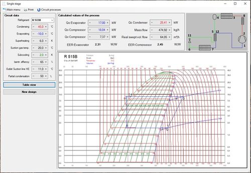
Calculations can be performed with all refrigerants here as well, including graphical representations of the circuit processes in a log(p)-h diagram. A thermodynamic table is also available.
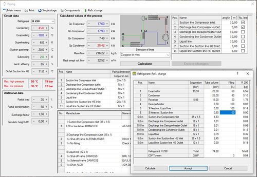
COOLSTAR provides all piping for the calculated circuit processes. The geodetic height difference is evaluated as a pressure loss or pressure increase. When selecting the suction or discharge line, COOLSTAR automatically verifies if all conditions for a perfect oil transport are fulfilled. If necessary, line tapering will be suggested. Furthermore, double rising lines can be calculated. The operating points are displayed in an oil diagram for visual control. The system only displays the possible and approved pipe types. All lines can be changed manually by the user.
At the same time, all required components – such as shut-off valves, solenoid valves, non-return valves, expansion valves, dryers and sight glasses – are designed, and the insulation required to prevent the dew point from being undershot is dimensioned. The calculation is rounded off by determining the refrigerant charge. The calculation results are clearly presented in tabular form.
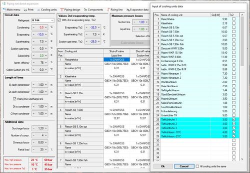
This module is specifically developed for compound systems. Within a very short time, you can design all refrigerant-containing piping in compound systems with up to 100 cooling units and up to 20 compressors, including suitable solenoid, expansion and shut-off valves. The system only displays the possible and approved pipe types. The suction line can be calculated with two different evaporating temperatures, especially for booster systems.
All other fittings for the compound (check valves, driers, sight glasses, etc.) are calculated as well. Pipe lengths and rising lines can be changed directly in the pipe diagram. Like in the calculation of pipelines, rising lines are verified for optimal oil transport; if necessary, the lines are tapered or split. Both the number of existing or required compressors and the factor of simultaneousness can be selected.
COOLSTAR draws up a list of material for the calculation, a list of piping for your fitters on the building site, a list of components for each cooling unit and a list of rising lines with the required double rising lines. Verifying calculations of existing piping networks are possible as well.
COOLSTAR allows you to calculate solenoid valves from the manufacturers
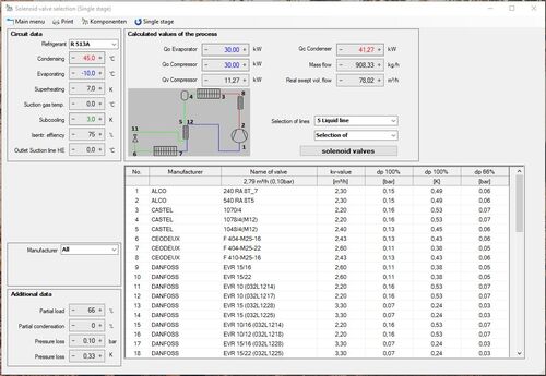
for liquid, suction gas and pressure gas lines. Valve images are displayed in the results lists and the documentation can be opened directly. Valves are selected covering the cv value and considering the minimum pressure drop for servo-controlled valves. Besides it is also possible to recalculate existent valves.
Products from manufacturers
are included. COOLSTAR allows you to calculate the most common valves from the above manufacturers. Valve images are displayed in the results lists and the documentation can be opened directly.
This module includes products from
Similar to expansion valves, check valves are selected covering the cv value and considering the minimum pressure drop. Recalculation of existing valves is possible as well. Valve images are displayed in the results lists and the documentation can be opened directly.
This module allows you to calculate refrigerant compressors from BITZER and BOCK. Typically, two compressors are suggested for selection, making it easy and quick for you to choose the most suitable compressor.
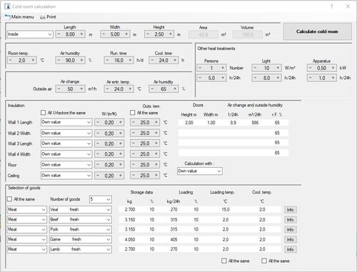
The calculation of cold rooms allows you to quickly determine the required refrigeration capacity. With this module, you can calculate coolers up to a dimension of 100m x 100m x 100m.
COOLSTAR includes the data of about 150 different cooling goods, so that the required information can be retrieved for almost any type of product. Calculations using data from your own goods is also possible.
The air change is calculated using either the BÄCKSTRÖM or TAMM formula, and you can also input your own values. When calculating the required refrigeration capacity, COOLSTAR automatically considers the effects of fan and defrost heaters, eliminating the need for tedious adjustments to account for effective operating hours.
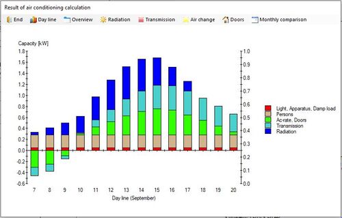
This module allows you to calculate the cooling load of air-conditioned rooms. Ground plans of any shape can be entered. The program takes into account the adaptation of indoor conditions to fluctuating outdoor temperatures, as well as factors like outside air change rate, glazing, number of people and sun protection. For July and September, the development of thermal loads in the air-conditioned rooms is shown.
COOLSTAR allows for the calculation of water networks with up to 100 cooling units, including the required components (shut-off valves, solenoid valves, check valves, circuit control valves, filters, two-way or three-way control valves).
COOLSTAR supports calculations with the specific data of the following refrigerants and brines:
Water, Antifrogen N, Antifrogen L, Antifrogen KA, Antifrogen KF, Fragoltherm oils, Fragol W-ECO Neo, HYCOOL 20 bis 50, Freezium, Glykosol N, Pekasol L, Pekasol 2000, Syltherm XLT, Temper -10 bis -60, Therminol D12, Thermogen, Tyfocor, Tyfocor L, Tyfoxit, Tyfoxit F, Zitrec MC, Zitrec LC.
The module includes components from the following manufacturers: ARI, BELIMO, BELVEN, BENDER, CIRCOR RTK, DANFOSS, ESBE, GEORG FISCHER, HERZ, HONEYWELL, MEIBES, NICAB, OEVENTROP, PARKER, RAMSAYER, SAUTER, SIEMENS, TACO, and TICOM. You can also enter your own data.
The piping network can be calculated with the help of pressure drop or flow velocity. The system only displays possible and approved pipe types. The loss of pressure of the respective heat exchanger is also taken into account.
The calculation of the chilled-water receiver is dynamic, depending on the coolant volume in the piping network. The required circulation pump's data is determined, and all selected heat exchanger components are adjusted accordingly.
COOLSTAR also calculates the insulation required to prevent falling below the dew point (AEROFLEX, ARMAFLEX, ISOPIPE, KAIFLEX, THERMAFLEX, and WÜRTH).
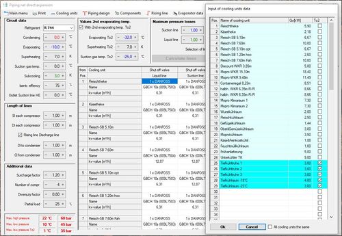
The module has the same functionality as module 5 “Calculation of piping network”, with the difference that only one evaporation temperature can be selected and the circulation factor and the pump pressure difference must be specified.
The pump flow and return lines are dimensioned according to the pipe network and the height difference between the cooling point and the separator. The return line can be divided into up to 3 partial lines at riser points. The boiling delay due to the pressure loss of the pipe network is determined at all cooling points. The valve stations for flow and return are designed for each cooling point. Up to 10 heat exchangers can be connected downstream of the valve stations.
Using this module, you can show the theoretical compression for pump refrigeration plants in a log(p)-h diagram. Calculation can be made for any refrigerant without temperature glide.
Pre-adjustments can be made in the following ranges:
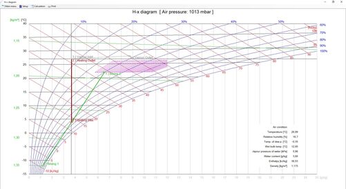
For every air condition, values for temperature, relative humidity, specific humidity, water vapour pressure, enthalpy and density, dew point and wetbulb temperature are shown. By entering two values, all other values are automatically calculated. The module calculates the following changes of the air: heating, cooling, dehumidifying, humidifying with scrubber or steam and mixing. In all calculations, the target value can be selected (air admittance and outlet, volume flow, or performances). Subsequent calculations can also be made. In this case, the air outlet value is taken as air admittance value of the subsequent calculation (e.g. mixing, heating, humidifying). The changes of state are displayed both in charts and tables.
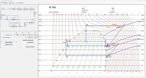
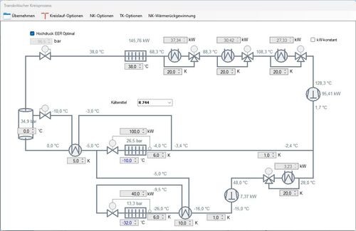
This module is designed for R744 (CO2), R23, and R170 only. The circuit process can be calculated as either subcritical or transcritical, with or without gas bypass. The system may include an internal heat exchanger and/or pressurised gas heating, with COP-optimised high pressure. Pipework is designed for maximum operating pressures. The circuit diagram can include a TC booster, pressure maintenance valve, or satellite compressor. In the NK circuit, heat exchangers can be selected for gas cooling or liquid subcooling, with up to three desuperheaters for heat recovery. In the TK circuit, heat recovery and an internal heat exchanger can be integrated. Pipework and components are dimensioned, allowing parallel connections of control or non-return valves.
